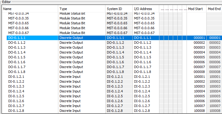
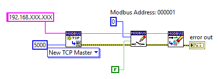
Modbus Address Structure - Coils & InputsThere is a few basics that have to be understood first before starting a connection with the Productivity 2000 PLC. From Automation Direct's website I found a good resource that explains how the Modbus addresses work. The address Identifier has a prefix that designates what the address type is. The remaining digits are the unique address channel. In order for LabVIEW to understand the address identifier it needs to be mapped to the PLC tag related to the Input or Output (IO). Below shows what identifier is used with the LabVIEW Modbus API VI. As stated each IO Modbus Address needs to be mapped to its corresponding tag. For this to happen the Productivity Suite software needs to be installed. During setup of the software configure your PLC chassis and connect to it over your local area network. On the left hand side of the software find "Write Program > Tag Database" then double click. Scroll down and find your tags for your IO cards. For this demo I am using the default tag names. Double click on the "Mod Start" and two numbers will show up. The left most number is the address type and the right is the address number. The address number can be any value, however it will auto assign and increment when clicking through the rest of the tags. After assigning tags close the Tag Database and "transfer project to CPU." Below is how I setup my tags: Now we should be ready to program LabVIEW! Lets Program!Use LabVIEW VIMP to download the Modbus Library. The library can be found under "Data Communication" > Modbus Library > Master API. We will start off with a simple coil write program. A coil is PLC language for a relay contact. Its also important to realize that LabVIEW is based on "0" index. This means the address that the desired address needs to be is subtracted by 1. Example: Modbus Address 000001-1 = LabVIEW Address 0. Also the Address identifier does not implicitly need to be stated, the Modbus VI adds this info at a lower level based on the type needed. Simple Coil Toggle
Now toggle the constant from TRUE to FALSE to turn off the coil, then run the program In the next post we will get into advanced programing techniques and test stand related programs.
0 Comments
Leave a Reply. |
Rocket Test Stand Controller ProjectThis blog will cover the development of my hybrid LabVIEW & PLC rocket engine controller. ArchivesCategories |


 RSS Feed